top of page
Nathan Selian: Mechanical Engineering
Motor Control Challenge
As our final project for ME360, we were challenged with creating a machine that could move an unsupported one foot bar of 80-20 aluminum extrusion five feet in one direction, then move back to where it started without toppling; all using a single DC motor and encoder as our motion source.
Reading The Encoder
To begin this project, we again broke out into our groups of 4 to learn how to control a DC motor. To start, we were given a 12V DC motor with encoder and an arduino, with which we would learn how to read the encoder on the back of the motor. In a nutshell, the encoder contains two disks with either holes or magnets at equally spaced locations, and either a hall effect sensor or light sensor in the encoder detects when these holes or magnets pass by them which outputs a small voltage. The locations of each disk are very slightly offset, so when the motor is spinning, the encoder produces a two channel signal that looks like two offset square waves. Since the square waves are offset, we can look at which channel outputs a voltage first to determine which direction the motor is spinning. We can also determine how much the motor has rotated by counting the amount of pulses that have passed by and in what direction the motor is spinning. With this knowledge we can write the following code to read the motor encoder.
Because we don't want to miss any of the pulses from the encoder we attach an interrupt to one of the channels with an encoder signal. This ensures that even if a blocking function such as delay() or some other part of the code is running when a pulse happens, we can interrupt that execution to run our encoder reading function (myFunction). Because this function is called when one of the encoder signals becomes HIGH, all the function has to do is check to see if the other encoder signal is also HIGH, and either increment or decrement a counter variable to indicate that the motor has moved one encoder pulse in either clockwise or counterclockwise. Knowing how many pulses are in one rotation, we can then convert the encoder count into an angle variable. Additionally, by calculating the change in angle over a set period of time, we can then calculate the RPM.
DC Motor Control
Once we had learned how to read the encoder, It was time to learn how to power and control the DC motor. For this we were given an L298N motor driver and a power supply to deliver power to the motor. Getting the motor to spin was very simple as all we had to do was apply a voltage to the motor terminals. Depending on the polarity of this voltage, the motor would either spin clockwise or counterclockwise; and by increasing or decreasing the voltage, we could increase or decrease the speed of the motor. In the code below, we were able to ramp the speed up and down in one direction, then do the same in the other direction.
One drawback to this method is that if a load is applied to the motor, the rpm's will drop while the applied voltage will stay the same. This isn't particularly good if we are trying to get the motor to spin at a certain rpm under different conditions; so to fix this, we must read the rpm of the motor and create a feedback loop to control the output voltage. There are a few ways to do this. One is a bang-bang control loop which checks to see if the rpm is above or below the target, then either applies all or no voltage to the motor depending on what is sees. This is a very crude method and can oftentimes result in an oscillating rpm. Another way is a PID control loop which looks at three parameters: how close (Proportion) is the rpm to the target, how fast (Derivative) is the rpm approaching the target, and cumulatively (Integral) how much the rpm has been different from the target. Without getting into the weeds of it, properly adjusting these three parameters to a system can result in both accurate, fast, and stable control. For our purposes, we will just look at the proportional control as without a dedicated PID controller circuit, it might be somewhat difficult to code one that works well on an arduino without a more formal knowledge of coding. However using the knowledge we do have, we were able to produce the code below.
Design and Simulation
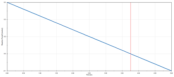
As part of this project, we were tasked with creating a simulation of our own model in SolidWorks. This comprised of creating a 3D model of our ideal car and all its components, then creating a motion study to analyze the forces on the aluminum extrusion under increasing acceleration to find a theoretical maximum acceleration for the car that kept the extrusion upright. I went with a laser cut box design for the chassis to give maximum stiffness, 3D printed wheels with rubber O-ring tires to maintain traction and hopefully absorb a tiny amount of vibration from unevenness in the floor, a belt and pully from the motor to the axle, and a simple clamping motor mount that would attach to slots in the chassis for easy belt tensioning. The electronics were given enough room to be mounted from laser cut holes underneath the chassis, hidden away for a clean design. For the simulation, I set a linearly increasing acceleration from zero to one m/s/s over five seconds. I then measured the reaction force between the front edge of the extrusion and the top of the chassis to look for when this value was zero as this would indicate the acceleration at which the extrusion would begin to topple. My car design and simulation results are shown below. The maximum theoretical acceleration from SolidWorks was found to be around 0.8 m/s/s.
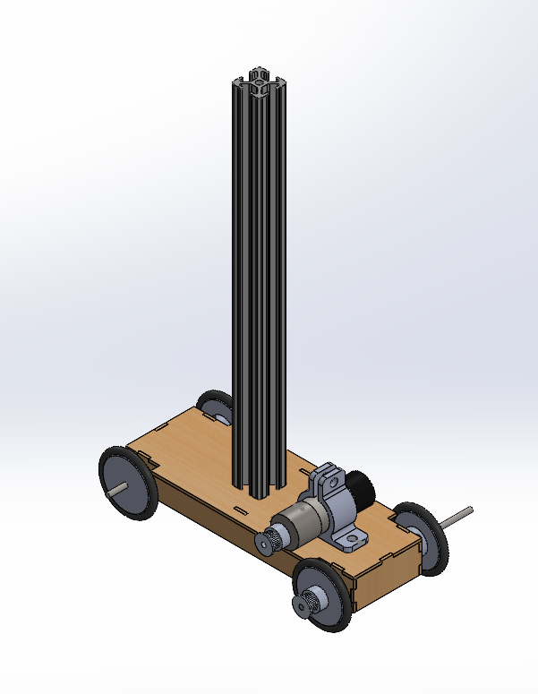
Isometric View
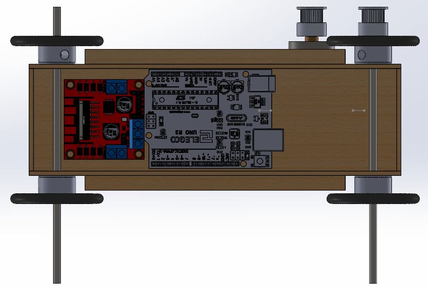
Bottom View

Isometric View
1/2

Putting it Together
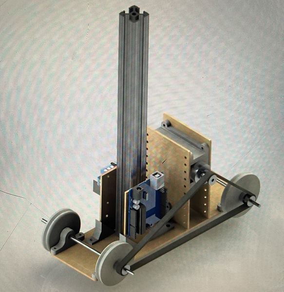
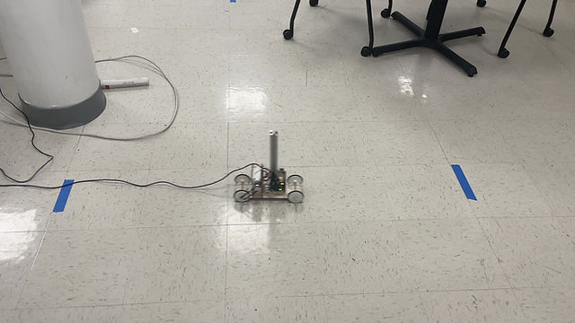
Once the simulations were complete, we began building our car. Our final design ended up being a conglomeration of all the parts we liked best about each other's individual designs. We stuck with the laser cut chassis, and opted for gluing four simple stringers to the bottom of the chassis to increase rigidity. We also mounted the electronics vertically for easy access which ended up being a very nice feature in testing. For the wheels, we stuck with the 3D Printed hubs with O-ring tires as most of us had included them in our individual designs and we were confident that they would be a good choice. The other group members thought it would be a good idea to drive the car from both axles, so a vertically adjustable motor mount was designed to allow for this. The motor mount had multiple sets of holes for height adjustment, which I wasn't super on board for as it would make adjusting the tension a more complicated and lengthy process than if we had used vertical slots.
For the code, I opted to write a fully closed loop program with proportional speed control. The target speed was set by reading the current speed, then incrementing the target speed by the target acceleration multiplied by the time since the last target speed increment. This ensured that the program would not request a target speed that exceeded our maximum target acceleration. The timing for acceleration and deceleration was based off the distance that the car had traveled which was calculated as a function of the wheel diameter and angular position of the motor. Additionally, to ensure smooth operation and transition between forward and reverse, min and max pwm voltages were set in the code. Also, since the Arduino cannot output a negative voltage with pwm, I had to write a few lines of logic to ensure that the proper pins were powered when either forward or reverse was needed. One parameter that I had to play with that had a large impact on the operation was the delay and timing of the rpm() function since this was the only delays() in the program, messing with this timing significantly changed the speed at which the feedback loop would operate. Ultimately I am happy with the functionality of the code, although I think if I had more time, I would've liked to clean it up a bit and convert some of the code in the void loop to functions, although this would certainly not make the code functionally better. The only functional improvement that after looking back I would've liked to implement would be to include the rpm calculation in the interrupted encoder reading function and base the time calculation of the arduino's internal clock count rather than a delay. Perhaps this would've made the interrupt function too intensive, however I did not try it to find out. The final code and video of the car is displayed below.
bottom of page


