top of page
Nathan Selian: Mechanical Engineering
Linear Stage & Frame Design
Similar to the pen plotter project, our pancake machine would be comprised of multiple linear stages to achieve the two required degrees of freedom. However, this time we would not be limited to foam board and hot glue, but instead would be using 80-20 aluminum extrusion and 3D printed components to build our machine. Like the pen plotter, we started off by designing a singular linear stage, although this time we would be using GT2 timing belts and pulleys to move the slider instead of a lead screw. Because of this, we needed to design a few components for 3D printing that would attach to the extrusion. This included a mounting bracket for a NEMA 17 stepper motor, another mounting bracket for the idler pulley, and a slider that we could attach either another linear stage or an end effecter to. For the stepper motor mounting bracket, we were able to use the standardized NEMA 17 mounting pattern with four M3 machine screws to mount the motor to the bracket. We also modeled in an aligning boss and used a 1/4-20 T-nut and machine screw to securely attach the bracket to the extrusion. The idler pulley bracket was attached to the extrusion in a similar way, as well as a hole was modeled in to accept a press fit 5mm metal shaft for the idler pulley to attach to. For the slider, we used the features of the extrusion as a linear guide rail and modeled bosses on the slider to interface with these features. We also modeled a clamping mechanism for the timing belt so that the belt could move the slider as well as so the belt could be properly tensioned.
One of the decisions that our group made that I did not agree with was the location that the belt would be positioned. In class we were warned that pulling on the slider too far away from the extrusion could cause a significant enough torque that the slider would bind up in the extrusion. In an effort to minimize the chances of binding, my group decided that we would position the belt in line with the extrusion. While this approach may have merits in other applications, for ours it only had drawbacks. First off, the belt clamp on the slider was located outside the extrusion, so there would still be a small torque applied to the slider. This would be no less than if the whole belt was positioned just outside the extrusion, which defeated the entire purpose of this decision in the first place. Second, because the diameter of the pulleys was smaller than the width of the extrusion, the belt clamp could not be placed in line from pulley to pulley. This not only meant that the angle of the belts would be applying a force to the slider outside the direction of movement, causing yet more friction; but it also meant that depending on the location of the slider, the belt would need to be different lengths to maintain the same tension. Additionally, this also meant that there would not be a linear correlation between the rotation of the stepper motor and the location of the slider. Realistically, all these factors would not be a huge issue for our purposes; however, one drawback to this decision that did become an issue was that the belt ran on both sides of the extrusion and the slider was attached at the top and bottom of the extrusion. This obviously made our options for mounting anything else to the extrusion extremely limited. Overall, I did not find it to be good engineering practices to incorporate all this complexity, uncertainty, and additional issues for limited to no gain.
For the frame, we used two parallel linear stages as the X-axis and connected them with two additional pieces of extrusion as cross bars. A third linear stage was connected to the sliders of the two X-axis stages as the Y-axis stage. To lift up the machine, four pieces of extrusion were attached to the cross bars as legs. These were attached by tapping the ends of the extrusion with a 1/4-20 tap, slotting 1/4-20 pan head screws into the cross bar extrusion as well as drilling access holes so that the screws could be torqued, then screwing the screws into the tapped legs. The same method was used to assemble and attach a frame which batter tanks could be later attached to.
End Effector Design
As part of the project, we would need to design a suitable end effector for our machine. For us, this meant designing something that regulate and control the dispensing of pancake batter onto a pan. Initially we came up with many different ideas for how we could accomplish this, but eventually ended up breaking it down into two methodologies. Either we could use gravity to dispense the batter and some sort of valve to regulate the flow; or we could design a peristaltic pump that could both dispense and regulate the flow. While we all agreed that a peristaltic pump would be the ideal choice, given our limited timeframe we were not certain that we could produce a working prototype in time. Because of this, we decided to take both routes as our main time limitation would not be design time, but rather 3D printing.
For the gravity fed design, we decided that we would mount a batter tank stationary above the moving components as we did not want to introduce extra weight to the linear stages. To accomplish this, I designed a 3D printed bracket to hold two condiment bottles that could be securely mounted to a piece of aluminum extrusion with 1/4-20 machine screws and T-nuts. To get the batter to the end effector, I ran some flexible and food safe silicone tubing from the nozzle of the condiment bottle that could eventually attach to the valve. For the valve, the other group members tried a design using a 3D printed lead screw that lined up two holes to allow flow. This ended up not working as they could not get the threads to engage well and it also would've been super messy. The next design was much better and simply used a stepper motor to twist and kink the silicone tubing to stop the flow. While effective, this design had one drawback. The silicone tubing was flexible enough to be kinked by the stepper motor, however when the motor was unpowered, the springiness of the tubing was strong enough to rotate the stepper motor and unkink the tubing. We looked into fixing this with software, however could not find an elegant solution.
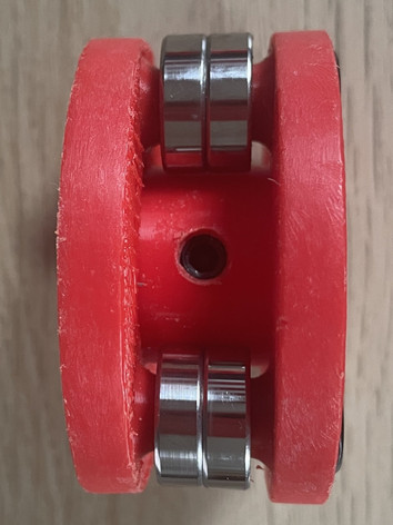
For the peristaltic pump, I designed it to work with the same flexible silicone tubing. The housing and rotor were 3D printed and designed to to work with a NEMA 17 stepper motor. On the rotor, I modeled in hexagonal pockets and countersunk holes to accept 1/4-20 flat head machine screws and nuts that ball bearings could be rigidly mounted to. I also modeled a hole into the rotor so that a set screw could be tightened to the motor shaft to prevent spinning. In the end, I was successful in getting the pump to operate; however the force required was on the limit of what the stepper motor could produce, so occasionally it would get stuck and require a nudge to get it spinning again. Unfortunately we did not have enough time to source a stronger motor, so in the end we decided to stick with the gravity fed system.

Electronics, Software, & Testing
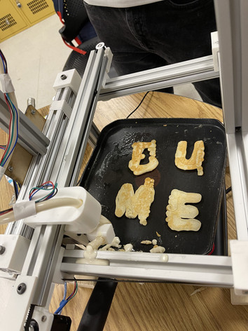
For the electronics and software, we largely used the same methods as used in the pen plotter project. For the MKS board, we laser cut a piece of bass wood so that we could attach the board to the frame of the machine. All the stepper motors were wired up to the MKS board and the wires were routed nicely along the frame of the machine. For the software, we used Repetier Host to communicate and send G-Code to the MKS board; and F-Engrave to convert images into G-Code. While the G-Code from F-Engrave did produce ok pancake shapes, I found that by manually modifying the G-Code, we could get even cleaner shapes and images.
The most difficult part of testing was dialing in the viscosity of the pancake batter to achieve optimal flow. This was difficult because as the batter sat, its viscosity would change as bubbles were produced from the ingredients of the pancake mix. The other parameters that we had to dial in were the speed that the end effector moved, as well as the heat of the pan below so that we did not burn the pancakes.
In the end, we were able to produce a variety of pancake designs including multiple circles, and most impressively the Boston University Mechanical Engineering logo.

bottom of page


